Measuring buildings, for the purpose of creating CAD drawings of them, is what I do for a living. It is something that I thoroughly enjoy doing, and each building is a challenge. I get great satisfaction out of trying to overcome such challenges, in order to provide my clients with accurate CAD drawings, in a timely manner.
In this post I’ll review a building measuring project that was more challenging than usual. This project was especially challenging because the building was way off being square. In other words, the wall to wall corners were not 90 degrees. No building is perfectly square, but this building was off more than normal.
Background
I was contacted by the owner of a multi-family walk-up building who was in need of floor plan and exterior elevation drawings of his building. The owner was considering making improvements to the building because it was in disrepair. He wanted the drawings so he could give them to his architect, I assume for the purpose of estimating the contemplated rehabilitation work.
Measuring
The building was constructed in the year 1900. That’s 111 years ago! Also, it was a really neat little property, with a super view overlooking a small park on the Upper West Side of Manhattan.
The building had crooked walls, and since it was pretty old the crooked wall condition was probably because of settlement over the years. Creating accurate floor plan drawings of it was challenging, due to the crooked walls. Crooked walls result in difficulties while drafting the floor plans, and require taking more measurements to establish the correct locations of walls.
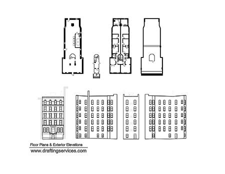
Project Summary
| Item | Description |
|---|---|
| Type and Location: | A 5 story multi-family walk-up residential building on the UWS of Manhattan. |
| Client: | Property Owner |
| Scope: | Create floor plan drawings of the basement, entrance / lobby, second floor, and roof. The first, and third thru fifth floors were considered repeats of the second floor.Also, create semi-scale building elevation drawings of all the building faces. |
| Area: | Basement = 2,092 sq.ft., Lobby = 287 sq.ft., Second Floor = 2,277 sq.ft., Roof = 2,502 sq.ft. |
| Was the space occupied with tenants?: | The areas that I need to access were vacant. However, the rest of the building was occupied. |
| Access Restrictions: | No, I met the Superintendant onsite, and he provided all necessary access. |
| Field Setup and Breakdown Time: | This time is lumped into my field time. |
| Field Measuring Time: | Total of floor plans (basement, lobby, second floor and roof) = 9 hours 22 minutes. |
| Field Measuring Time: | Total for building elevations = 8 hours 13 minutes. |
| CAD Drafting Time: | Total of floor plans (basement, lobby, second floor and roof) = 16 hours 7 minutes. |
| CAD Drafting Time: | Total for building elevations = 6 hours 21 minutes. |
| Total Travel Time: | 5hr (two trips) |
| Misc. Time: | 1hr of project coordination. |
| Crew Size: | 1 man |
| Equipment Used: | Hand held laser, tape measure, camera (optional), pens, pencils, eraser, paper and foam board. |
| Comments: | The second floor plan would be considered a dense layout. That means there were numerous rooms per square foot. |
| Total Time Spent on Project: | 46 hours 3 minutes |
Contact
If you have any questions about this project, or if you’re in need of drafting services, then please feel free to call me anytime. Call Now: 718.441.3968 or email at: brian@draftingservices.com