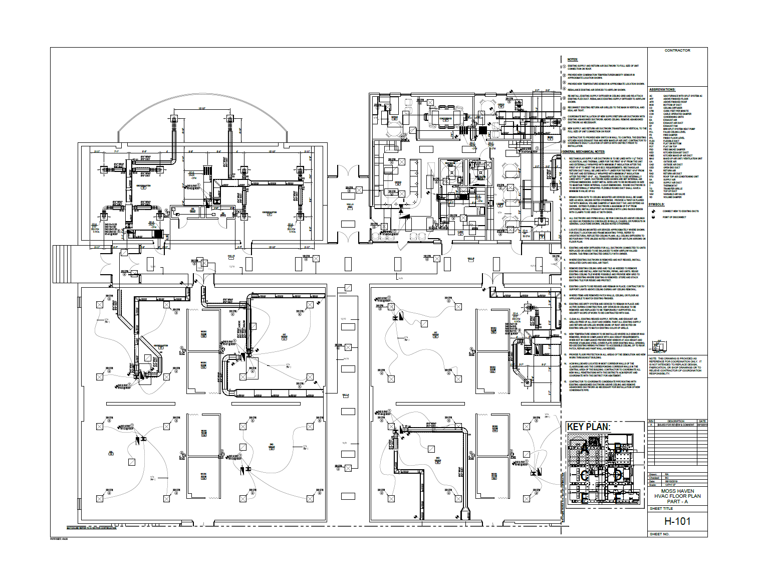
Below is a sample of one of my recent ductwork shop drawing projects. I created these shops for a mechanical contractor. This mechanical contractor provides mechanical services for new construction, rehabilitation, repair, and maintenance projects for institutional heating, ventilation, and air conditioning systems. I thought I could create a step-by-step guide for new drafters, on how to create ductwork shop drawings like my sample below. So here it is.

Best Procedure to Create Ductwork Shop Drawings
Producing HVAC shop drawings is a meticulous process that requires attention to detail and coordination with other construction disciplines. Below is a comprehensive guide to ensure the creation of accurate and complete HVAC shop drawings, leading to a successful and efficient installation process.
Discuss the Scope of Work
Begin by clarifying the scope of work. Determine if the project involves only HVAC systems or includes additional piping work. Confirm the need to coordinate with other disciplines, such as electrical, plumbing, and structural, by acquiring their shop drawings for reference.
Steps to Produce HVAC Shop Drawings
- Obtain HVAC Design Drawing PDFs: Collect the HVAC design drawings in PDF format to determine scope of work. Additionally, acquire structural and architectural PDF files to understand ceiling heights and beam & column locations.
- Inspect Design Notes for Insulation Details: Carefully review the design drawings to find insulation or liner details in the general notes or elsewhere. Confirm these details with the client to prevent rework.
- Account for Equipment: Find equipment schedules in the design drawings and extract equipment model numbers. Request equipment cut sheets and approved equipment submittals. Find equipment cad files over the internet or create equipment drawings with the help of cut sheet dimensions.
- Acquire CAD Files: Request CAD files of the design drawings from the architect of record. If unavailable, convert the PDF design drawings to CAD format and organize the layers appropriately. The architectural plans will typically be used as the basis for the shop drawing plans.
- Clean Up CAD Files: Remove any unnecessary text, layers, annotations, or etc. from the CAD files, to streamline the shop drawing creation process.
- Set Up Layout: Confirm desired sheet size and title block format. Ensure that the floor plan fits within a 1/4″=1’-0” scale. If not, create matchline views of the floor plan.
- Create Insulation Layers: Establish layers specifically for insulation or liners within the CAD files.
- Color Code Ductwork: Separate supply, return, exhaust, and outside air ducts using different colored layers for clarity.
- Add Insulation and Update Ductwork: Incorporate insulation or liner details into the ductwork. Transition single-line flex ducts to accurate double-line representations.
- Include Duct Cut Lengths: Add duct cut lengths, typically 59” for rectangular ducts and 60” for round ducts, ensuring they do not interfere with boot take-offs.
- Specify Duct Elevations: Use architectural elevations to specify the top and bottom of ducts, maintaining a minimum height of 6″ above the false ceiling to allow for light fixtures mounted within the false ceiling, if light fixture heights are not known. Rule of thumb is to keep ducting as high as possible, no matter what.
- Add Annotations and Tags: Include annotations and tags indicating duct sizes, materials, and other pertinent information.
- Equipment: Larger projects will need a roof plan showing HVAC equipment. Confirm equipment placement considering accessibility and maintenance needs. Include equipment schedule specifying details like make, model number, and performance characteristics.
- Verify with Design Drawings: Cross-check the shop drawings against design drawings to ensure accuracy and completeness.
- Coordinate with Other Disciplines: Engage with other disciplines such as electrical, plumbing, and fire suppression to ensure a clash-free installation.
- Conduct Quality Control Checks: Perform thorough quality control checks to confirm that the shop drawings meet project requirements and any other applicable standards.
- Publish Final Drawings: Convert the finalized shop drawings to PDF format and distribute them to the client and stakeholders for approval.
- Revise Shops Based on Feedback: Make necessary revisions and updates based on feedback from the client and other stakeholders.
- Finalize for Fabrication and Installation: Once all revisions are completed and the drawings are approved, use the shop drawings for fabrication and installation.
Summmary
By adhering to these steps, you can ensure that your HVAC shop drawings are precise, comprehensive, and align with project requirements, ultimately contributing to a streamlined and effective installation process.
My Drafting Services
If you’re in need of shop drawings like this, then please visit my Ductwork Shop Drawings service webpage to learn how to get me started on your project.
