
A mechanical contractor I have worked with on previous projects hired me to prepare HVAC ductwork shop drawings for a renovation project at Building 20 in the Brooklyn Navy Yard in Brooklyn, NY. My name is Brian, and I have over 18 years of experience creating HVAC and ductwork shop drawings for mechanical contractors throughout the United States.

The project began with ductwork serving two fan coil units on the second floor and later expanded to include additional exhaust and return-air ductwork on the first and second floors. Below is an overview of the project and how the shop drawings developed as field information and additional scope were provided.
HVAC Shop Drawings for Two Fan Coil Units
The contractor originally contacted me to prepare a shop drawing for a specific portion of the second floor. He provided the mechanical contract drawings and told me that he would follow-up with field markups showing top-of-duct heights and equipment information. He didn’t want me to start my shop drawings before he gave me that info.
This is typically how this contractor prefers to work with me on renovation projects. Rather than having me determine the final routing directly from the contract drawings, his field crew review the existing conditions and provide markups showing how they intend to install the ductwork. I then use those markups along with the contract drawings, CAD backgrounds, equipment submittals and field pics and videos to create the shop drawings.
That distinction was important on this project. The mechanical contract drawings themselves state that the drawings are diagrammatic and show the general arrangement and approximate size and location of the ductwork and equipment. Field coordination is required to accommodate the actual building conditions.
For the original scope, the contractor sent me the contract CAD files, fan coil unit submittals, marked-up mechanical drawings, architectural ceiling details, photographs and a video of the construction space.
Fan Coil Units and Supply Ductwork
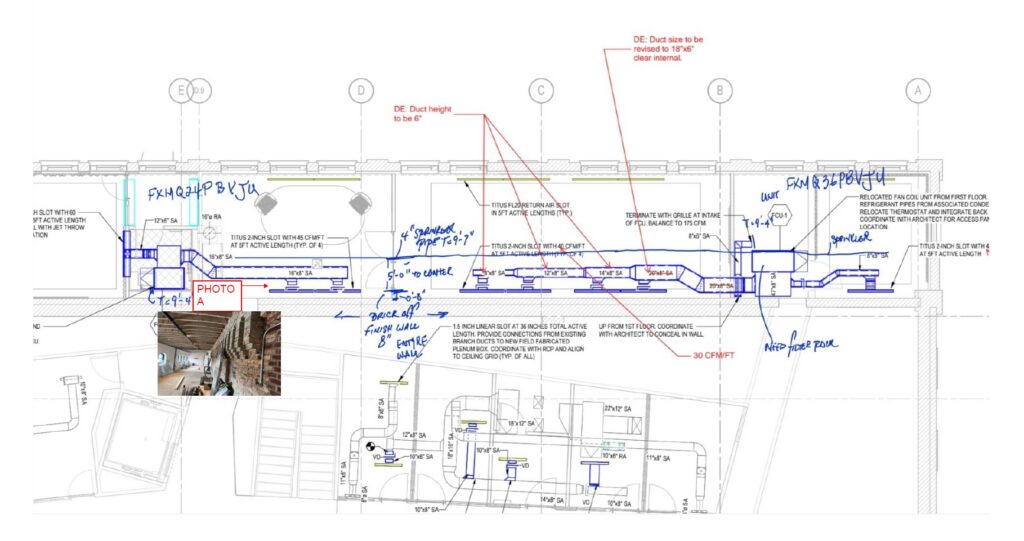
The two relocated fan coil units were Daikin concealed ducted units. FCU-1 was a 2-ton FXMQ24PBVJU and FCU-2 was a 3-ton FXMQ36PBVJU. The equipment submittals were used to establish the actual dimensions and connection locations for the shop drawing.
The 2-ton unit measured approximately 11-13/16 inches high by 39-3/8 inches wide by 27-9/16 inches deep. The 3-ton unit had the same approximate height and depth but was 55-1/8 inches wide.
The supply ductwork serving the two units consisted primarily of rectangular ductwork connecting to linear slot diffusers. The contract drawings included duct sizes such as 20″x8″, 16″x8″, 14″x8″, 12″x8″, 10″x8″ and 8″x8″, along with the transitions and branches required to distribute the supply air. The design also included Titus linear slot diffusers with different active lengths and airflow requirements.
During the development of the shop drawing, the contractor asked me to revise the ductwork to include 1″ acoustical liner. This was an important detail because the duct dimensions shown on the mechanical plans represented the clear inside dimensions of the lined ductwork.
As the shop drawing progressed, additional field requirements were identified. The contractor asked me to move FCU-1 approximately 6 inches toward the wall to provide enough room for a filter rack behind the unit. FCU-2 also had to be moved approximately 6 inches to provide space for its filter rack.
An 8″x6″ outside-air riser was also added next to FCU-1. The contractor asked that the riser terminate adjacent to the return section of the fan coil unit and that this duct also receive 1-inch acoustical liner.
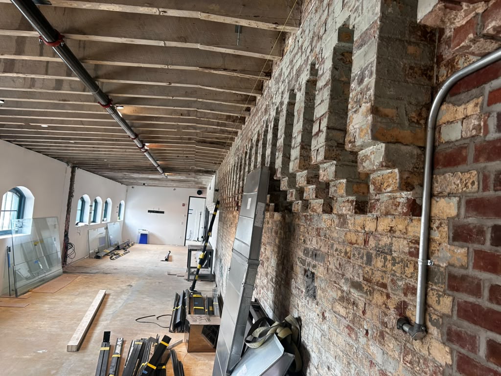
The contractor then sent me a field photograph showing the actual location where the 8″x6″ riser would enter the space. Because of the existing brick construction, the riser could not simply run tight against the wall. He instructed me to transition the duct approximately 8 inches away from the wall to clear the brick.
The contractor also identified an existing 4-inch sprinkler pipe running through the room and asked me to show it on the shop drawing as a reference. This was another existing condition that had to be considered when establishing the final duct routing.
This type of information is why field markups and photographs can be so important when preparing ductwork shop drawings for an existing building. A contract drawing can show where a duct is intended to go, but it does not necessarily show every sprinkler pipe, existing utility, wall condition or obstruction that the installer is dealing with in the field.
First Ductwork Shop Drawing
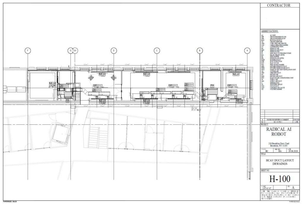
Using the contractor’s markups, field information and equipment submittals, I prepared the original HVAC ductwork shop drawing for the two fan coil units.
The drawing showed the coordinated locations of FCU-1 and FCU-2 along with the rectangular supply ductwork, transitions, return-air connections, linear slot diffuser connections, outside-air riser and the relevant existing conditions.
The first shop drawing was issued for review on June 29, 2026.
At that point, the original shop-drawing scope was completed. Then the project changed again when the contractor contacted me about additional HVAC work.
Additional Exhaust and Return-Air Ductwork
The contractor subsequently emailed me that an additional scope had been added to the project and asked me to provide a price for another set of shop drawings.
The revised contract drawings identified the new work, but once again the contractor did not want me to immediately begin laying out the ductwork based solely on the contract drawings. He was waiting for his field crew to inspect the areas and prepare markups.
Once those markups were completed, he sent them along with additional photographs, videos and dimensions showing the actual conditions in the building.
I think this is an important part of the project because the field information wasn’t supplemental decoration for the shop drawings. It was part of the process used to establish the actual duct routing.
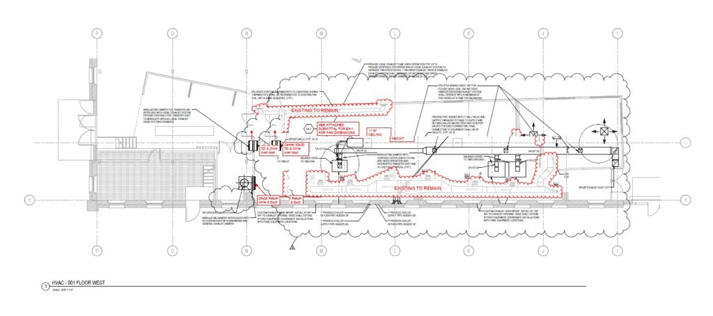
The additional work covered three areas: 001 Floor North, 001 Floor West and 002 Floor West.
001 Floor North – Exhaust Ductwork
The new work on 001 Floor North included exhaust ductwork serving two EA-2 exhaust connections and one EA-1 exhaust connection.
The contractor instructed me to route the new exhaust ductwork tight to the ceiling. Unlike the acoustically lined fan coil ductwork in the original scope, these exhaust ducts were to be uninsulated.
The field photographs were useful because this was an exposed-ceiling space with existing ductwork, sprinkler piping, lighting, structural members and other building systems already occupying the overhead area.
The field video above shows the existing conditions in this portion of the building and the overhead space where the new exhaust ductwork had to be installed.
Instead of trying to infer the available space from a two-dimensional contract drawing, I could use the field information provided by the contractor to prepare the ductwork shop drawing around the existing conditions.
001 Floor West – Exhaust and Return Air
The 001 Floor West portion included changes to both the exhaust and return-air systems.
The project included localized exhaust serving the workshop areas. These systems were intended to capture and remove contaminants at individual work areas rather than relying solely on general room exhaust.
For the shop drawings, the contractor directed us to revise the transfer and return-air routing shown on the contract drawings. This area included a 26-inch round return-air riser with 1-inch acoustical liner.
The new exhaust ductwork was again to be installed tight to the ceiling. The contractor specified uninsulated exhaust ductwork with TDC connections.
The final shop drawing for this area contains a substantial range of duct sizes and fittings. Rectangular duct sizes include 38″x18″, 22″x18″, 20″x16″, 18″x8″, 16″x14″, 14″x8″, 11″x8″ and smaller branches serving the individual air devices.
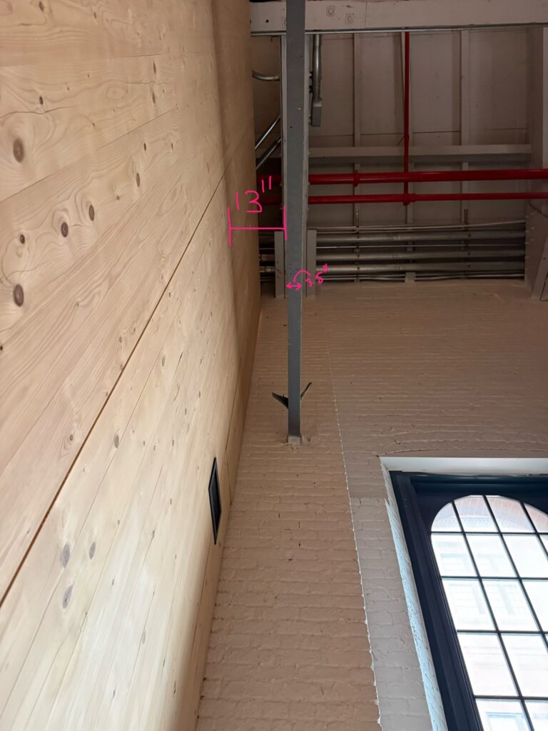
One of the photographs provided by the contractor showed approximately 13 inches of clearance between the wall and an existing vertical member. It is a simple field dimension, but it illustrates why this type of coordination matters. There isn’t unlimited space available to move ductwork around when working in an existing building.
002 Floor West – Existing Return-Air Connection
The additional scope also extended to 002 Floor West.
This area included new ductwork along with modifications to the existing return-air system. A 26-inch round return-air duct was part of this portion of the work, and the contractor instructed us to reconnect the return-air duct to the existing ductwork in the field.
The final shop drawing also shows the relationship between the new work and a variety of existing supply-air ductwork, including 22″x12″, 20″x14″, 18″x12″, 16″x14″, 14″x10″, 12″x8″, 11″x8″ and smaller branches.
The process-chiller work appearing on the mechanical contract drawings was specifically identified by the contractor as not being part of our scope.
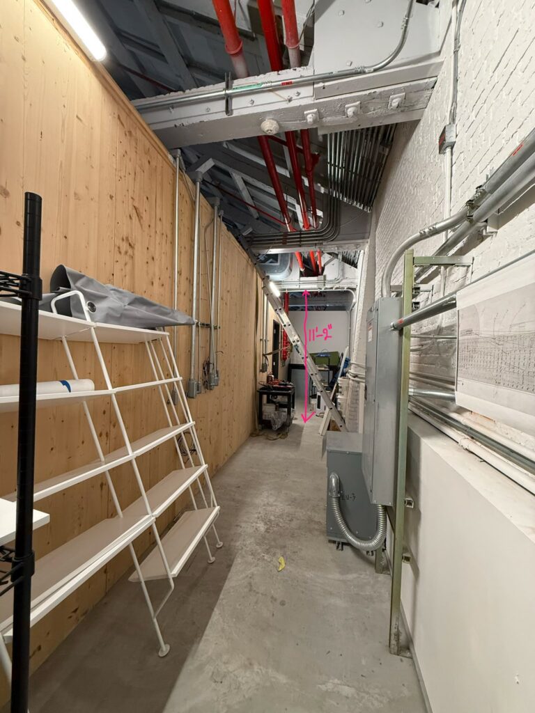
Again, the field photograph helps explain the drawing better than a paragraph can. There are sprinkler pipes, electrical conduit, structural framing and other existing utilities occupying the overhead space where the ductwork has to be installed.
The contractor’s photograph established an available height of approximately 11′-2″ in this area. That information, together with his marked-up routing, provided the basis for coordinating the new ductwork with the existing conditions.
From Contract Drawings to Field-Coordinated Shop Drawings
This project is a good example of how I work with mechanical contractors on renovation projects.
The engineer’s mechanical drawings establish the design requirements and general system layout. On this project, the contract documents specifically state that the mechanical drawings are diagrammatic and show the general arrangement and approximate size and location of the ductwork and equipment. They also place responsibility on the contractor to coordinate the installation with the other trades and actual field conditions
The contractor is in the building and knows how he intends to install the system. On this project, he supplied field markups, photographs, videos, equipment submittals and dimensions. I used that information together with the contract documents and CAD backgrounds to prepare the coordinated shop drawings.
The project evolved along the way. Fan coil units moved 6 inches to accommodate filter racks. Ductwork was changed to include 1-inch acoustical liner. An 8″x6″ outside-air riser was added and then offset 8 inches to clear existing brick. Existing sprinkler piping was identified for coordination. Later, an entirely new exhaust and return-air scope was added and field-verified before I began the additional drawings.
Those are the details that turned the mechanical design into shop drawings reflecting how the contractor intended to install the ductwork.
Brooklyn Navy Yard HVAC Shop Drawings
The final additional-scope package consisted of three 48″x36″ HVAC duct layout drawings covering 001 Floor North, 001 Floor West and 002 Floor West. The drawings show the coordinated duct routing, duct sizes, fittings, transitions, equipment connections and relevant existing conditions for the mechanical contractor’s installation.
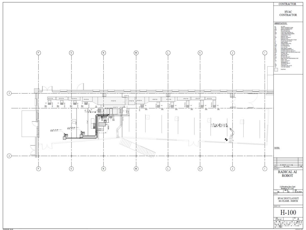 Click the image above to view the HVAC ductwork shop drawings for the Brooklyn Navy Yard Building 20 project in PDF format.
The Brooklyn Navy Yard project started as a relatively small ductwork shop drawing assignment for two fan coil units and expanded as additional work was added. By the end of the project, the drawings incorporated multiple field markups, equipment submittals, existing conditions and revisions provided by the contractor. This type of back-and-forth coordination is a normal part of preparing HVAC shop drawings for renovation projects.
Contact
If you are a mechanical contractor and need HVAC or ductwork shop drawings for a renovation or new construction project, feel free to contact me to discuss your project.
You can call me at 718.441.3968, text me at 646.504.5230, or email me at brian@draftingservices.com.