My name is Brian and I provide structural steel shop drawings for projects throughout the United States. I have over 18 years of drafting and steel detailing experience.
In early May I was contacted by a general contractor regarding structural steel shop drawings for a new one-family home located in Garden City, New York. Below is an overview of the project, including the shop drawings I created for it.
Project Overview
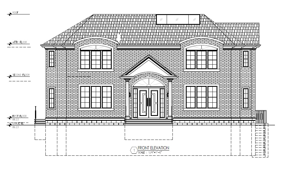
This project involved the construction of a new two-story residence with a full basement. The proposed basement floor area was approximately 2,518 square feet, the proposed first floor area was approximately 2,277 square feet, and the proposed second floor area was approximately 2,040 square feet, yielding a total livable area of approximately 4,317 square feet.
I enjoy discussing actual projects because they often bring up real coordination issues and conditions that occur during the steel detailing process. In this project an interesting issue came up involving connection revisions and also the timing of when fabrication drawings should be created.
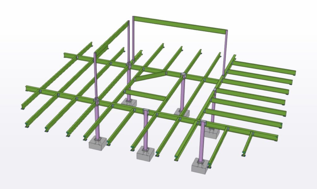
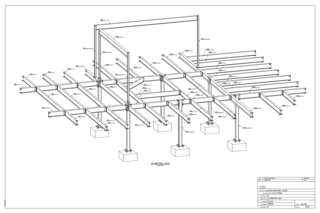
The structural steel framing for this project was concentrated primarily on the first floor level. There were only two beams located at the second floor level and those members transferred loads through columns down into the framing below.
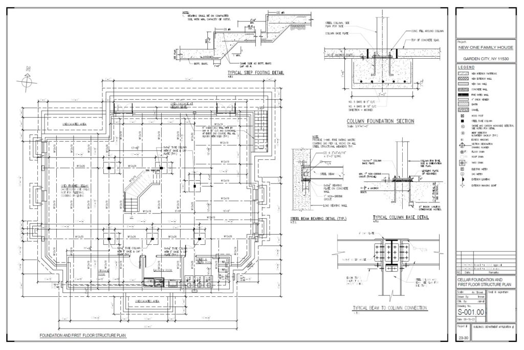
The project contained approximately 45 steel beams and 10 steel columns. Most of the steel beams consisted of W12x19 members supported either by reinforced concrete foundation walls or steel columns located within the basement area.
The steel columns stood on 14″ x 14″ x 1″ thick base plates with four 3/4″ diameter j-hook anchor bolts that were cast-in-place into reinforced concrete footings. The footings supporting the columns measured approximately 3′-0″ x 3′-0″.
Steel Modeling and Erection Drawings
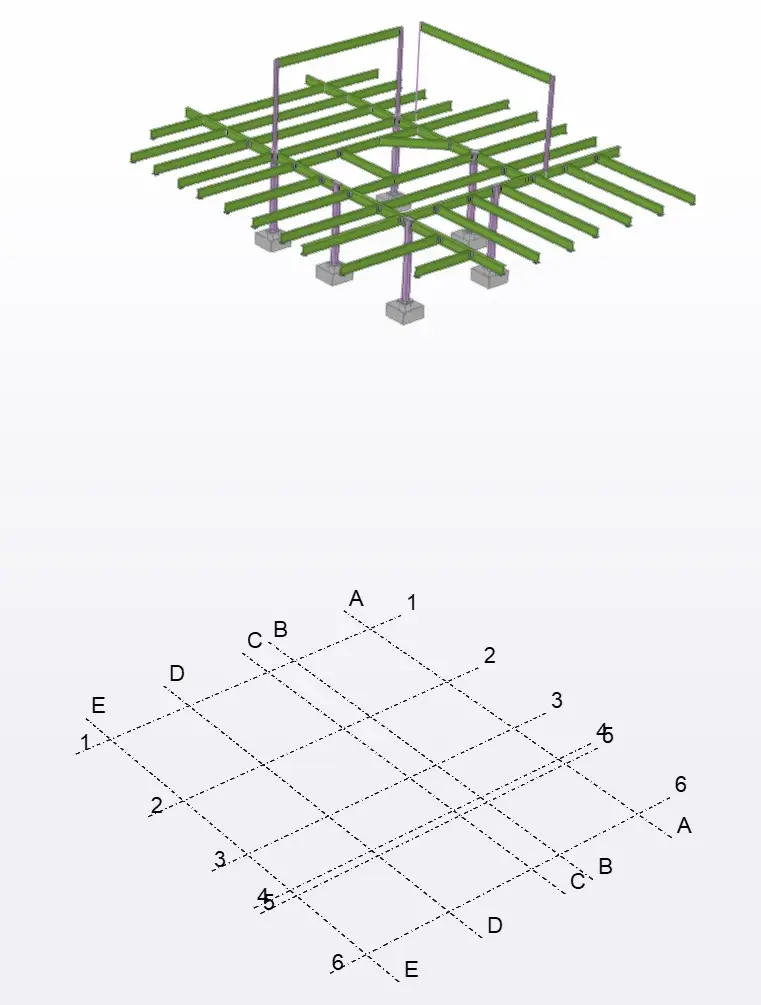
For this project I created the structural steel detailing package from scratch and developed a three-dimensional model using Tekla Structures.
Creating the model allowed the structural framing and connection conditions to be coordinated before producing the erection drawing package. Modeling the steel in three dimensions also allows potential issues to be identified before fabrication and construction begin.
After the steel model was completed, the erection drawings were generated and submitted to the Architect of Record for review. Click on the image below to view the complete PDF set of erection drawings.
Connection Coordination
During the review process several connection revisions were requested.
After reviewing the proposed modifications, we found that some of the requested changes introduced constructability concerns and created member interference issues. Some revisions would also have resulted in beam lengths approaching approximately 40 to 50 feet.
While longer members can certainly be fabricated, on a residential project of this size they can create practical transportation and erection considerations.
After several rounds of emails I suggested a different approach to help move the project forward. Rather than continuing to revise individual connection conditions one at a time, we proposed detailing the connection conditions in a way that addressed the concerns being discussed while also avoiding framing conflicts and constructability issues.
The revised connection details were then resubmitted to the Architect of Record for review and approval.
The revised details eliminated member clashes and we also provided the IFC model file so the project team could review the framing and connection conditions in a three-dimensional environment.
The erection drawings were subsequently approved.
Fabrication Drawings Pending
The contractor was working on an accelerated schedule and requested expedited work to help move construction forward. Because of this, the erection drawings were completed and approved while foundation work was still underway.
At this stage, however, the fabrication drawings have not yet been created.
The structural notes for the project specifically stated that the shop drawings were to be based upon field verified conditions. This is an important point because the steel framing in this project relies on foundation walls, reinforced concrete footings, cast-in-place anchor bolts, column base plates, and beam bearing locations all aligning properly.
Prior to proceeding with fabrication drawings, I recommended allowing the foundation construction to be completed and then having a land surveyor document the as-built conditions of the foundation walls, footings, and anchor bolt locations.
Once construction is complete and those dimensions are verified, then fabrication drawings can proceed with greater confidence that the fabricated steel will match the actual field conditions.
Contact
I enjoy discussing actual projects because every project tends to bring up something different. In this particular project there was a combination of steel modeling, connection coordination, accelerated scheduling, and field verification considerations.
If you require structural steel shop drawings, steel detailing services, erection plans, or fabrication drawings for your project, feel free to contact me and I would be happy to discuss your project requirements.
Contact me today at 718.441.3968, text me today at 646.504.5230, or email me today at brian@draftingservices.com.